Guide to understanding (WPS), (PQR), (WPQR)

Introduction
Welding requires skill. Determining “how to weld” requires knowledge regarding the materialsbeing welded and welding process, among numerous other factors. Because of huge numberof variables involved, the knowledge of the welding engineer and the skill of the welder needto be validated by a series of tests. All this information is documented on Welding ProcedureSpecification (WPS), Procedure Qualification Record (PQR), Welding ProcedureQualification Record (WPQR), and associated Test Reports.What is Welding Procedure Specification (WPS)? A WPS is a document that describes how welding is to be carried out in production. Itspurpose is to aid the planning and quality control of the welding operation. They arerecommended for all welding operations and most application codes and standards makethem mandatory.What is Procedure Qualification Record (PQR)? A PQR is required when it is necessary to demonstrate that your company has the ability toproduce welds possessing the correct mechanical and metallurgical properties. A welding procedure must be qualified in accordance with the requirements of an appropriatewelding procedure standard, such as ASME Sec IX, as follows:1. Produce a welding procedure specification (WPS) as stated above.2. Weld a test piece in accordance with the requirements of your specification. The jointset up, welding and visual examination of the completed weld should be witnessed bya certified welding inspector such as an AWS certified CWI or an Inspection Body.The details of the test such as the welding current, pre-heat etc., must be recordedduring the test.3. Once the welding is complete the test piece must be subject to destructive and nondestructive examination such as radiography and mechanical tests as defined by thewelding procedure standard. This work must be carried out in a qualified laboratorybut the Inspection Body may require witnessing the tests and viewing anyradiographs.4. If the test is successful you or the test body completes the appropriate documentswhich the test body’s surveyor signs and endorses.
What information should they include?
Sufficient details to enable any competent person to apply the information and produce a
weld of acceptable quality. The amount of detail and level of controls specified on a WPS is
dependant on the application and criticality of the joint to be welded.
For most applications the information required is generally similar to that recorded on a
Procedure Qualification Record (PQR), except that ranges are usually permitted on
thicknesses, diameters, welding current, materials, joint types etc.
If a WPS is used in conjunction with an approved procedure qualification record (PQR) then
the ranges stated should be in accordance with the approval ranges permitted by the PQR.
However careful consideration should be given to the ranges specified to ensure they are
achievable, so that these ranges represent good welding practice.
What is a Prequalified WPS?
Some codes, such as AWS D1.1, allow “Prequalified WPS”, whereby it is established that the
WPS written per code will produce welds with correct mechanical and metallurgical
properties. It is not necessary to prepare a PQR in such cases. However, the pre-qualified
WPS have a specified range of parameters under which the weld must be produced. When
welding variables fall outside these ranges, a WPS with supporting PQR must be prepared.
What are SWPSs?
In an effort to standardize and harmonize the process of WPS approvals, AWS started
writing “Standard Welding Procedure Specifications (SWPSs)” with input from the pioneers
and experts in the welding industry. An extensive testing program was undertaken whereby;
these SWPSs were then supported by numerous PQRs.
When the use of SWPSs is permitted by referencing code section, your company does not
have to perform one or more procedure qualification tests. You can simply purchase the
applicable SWPS for unlimited intra-company use from the American Welding Society
(www.aws.org).
What is Welder Performance Qualification Record (WPQR)?
Once the procedure is approved it is necessary to demonstrate that all your welders working to it have the required knowledge and skill to put down a clean sound weld. If the welder has satisfactorily completed the procedure test then he is automatically approved but each additional welder must be approved by completing an approval test to an appropriate standard such as ASME Sec IX as follows:
1.Complete a weld test as stated above. The test should simulate production conditions and the welding position should be the position that the production welds are to be made in or one more severe.
2. For maximum positional approval a pipe inclined at 45 degrees (referred to as the 6G position) approves all positions except vertical down.
3.Test the completed weld in accordance with the relevant standard to ensure that the weld is clean and fully fused.
4. For a butt weld this is normally a visual examination followed by radiography or bend tests.
5.Once the test is completed the necessary forms have to be completed by you or the test body and signed by the test body’s surveyor.
6. Note that any changes that require a new welding procedure (WPS) may also apply to the welders approval, refer to the referencing code/ standard for precise details
Acceptance Standards
In general welds must show a neat workman like appearance. The root must be fully fused along the entire length of the weld, the profile of the cap should blend in smoothly with the parent material and the weld should be significantly free from imperfections. Reference should be made to the acceptance standard for precise details.
Documentation
The necessary documents for a successful Welding Program are as follows:
1.Welding Procedure Specification (WPS), Procedure Qualification Record (PQR), Independent Laboratory Test Report for the PQR, Welder Performance Qualification Record (WPQR), and Independent Laboratory Test Report for the WPQR; OR
2.Pre-qualified Welding Procedure Specification (Applicable to some Codes only), Welder Performance Qualification Record (WPQR), and Independent Laboratory Test Report for the WPQR; OR
3.Code adopted Standard Welding Procedure Specification (SWPS), Welder Performance Qualification Record (WPQR), and Independent Laboratory Test Report for the WPQR
PQR/ WPQR Testing
The following tests by Independent Test Laboratory may be required on your PQR and WPQR Coupons:
Weld Visual Examination by a AWS Certified Welding Inspector
Bend Test
Hardness Test
Transverse Tensile Test
All Weld Metal Tensile Test
Charpy Impact Test
Weld Metal Chemical Analysis
Macroetch Test
Torque Test
Peel Test
Nick Break Test
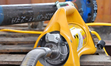
Radiography Test
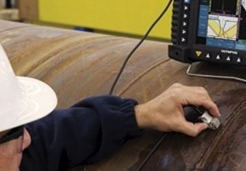
Ultrasonic Test
Weld Inspection and Testing
In addition to the above, you may require independent inspection of the welds by the following qualified personnel:
Visual Inspection by AWS Certified Welding Inspector (CWI)
Radiographic Testing by Level II personnel certified as per SNT-TC-1A
Ultrasonic Testing by Level II personnel certified as per SNT-TC-1A
Magnetic Particle Testing by Level II personnel certified as per SNT-TC-1A
Penetrant Testing by Level II personnel certified as per SNT-TC-1A
AEIS can perform the above tests at your facility or at our laboratory.


Recent Comments